Binary Distillation Column Simulator
Dual composition control of a binary distillation column. The process is a 2×2 MIMO system: reflux (L) and vapor boil-up (V) manipulate distillate (y1) and bottoms (y2) composition. Based on Module 13 of Process Control: Modeling, Design, and Simulation by B. Wayne Bequette.
Variables are dimensionless deviation variables from the nominal operating point: y1 = 0.99 (xD), y2 = 0.01 (xB), L = 2.706, V = 3.206 kmol/min. Sliders show physical changes in flow rate; the simulation works internally in deviations.
Process Schematic (Module 13)
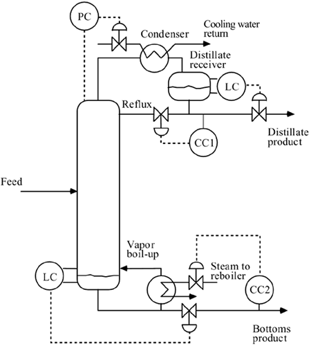
Figure M13-1 from Bequette, showing the column, condenser, reflux drum, reboiler, and the manipulated (L, V) and disturbance (F, zF) streams. Live values are shown in the metric cards in the Closed-Loop Response panel.
Closed-Loop Response
Inputs & Disturbances
IMC PI Tuning
Loop 1: y1–L
Loop 2: y2–V
Recommended pairing from the RGA: y1 controlled by reflux L, y2 controlled by vapor boil-up V. High RGA (~35) means the loops are strongly interacting; decoupling is needed for tight control.
Open-Loop Analysis (SVD)
The steady-state gain matrix maps inputs to outputs . Singular value decomposition reveals which input directions produce the strongest (and weakest) output response. Based on Bequette Module 13, Figures M13-4 through M13-6. See the tutorial →
SVD Summary
Response updates automatically when sliders change or a preset is selected.
Static-gain ellipse (y = K·u, output space)
The ellipse is the image of the unit-circle input direction under K. The thin axis is vlow (σmin ≈ 0.014) — the direction that nearly cancels both outputs. The dot marks the current y. Sign-flip boundary: y1 flips when the dot crosses the y2-axis; y2 flips when it crosses the y1-axis. The vlow axis (input angle ≈ 45°) is where both cross at once — that is why a small slider nudge near 45° produces an apparent sign jump. See the direction-sensitivity tutorial for the full geometric picture.
Process Model (Module 13)
Input-output transfer function model for dual composition control:
Relative Gain Array for the L–V pairing:
IMC-based PI tuning for each first-order loop (designed independently):