Independent Fuel Air Ratio Protection in Burner Management System
Introduction
Fuel safety in industrial boilers, fired heaters, and other furnaces is essential for achieving safe operation of chemical and hydrocarbon processing plants. To achieve high safety standard and minimize the risk, mandatory fuel safety codes and requirements must be strictly complied to obtain regulatory approval of fuel appliances. In the United States, the main approval code for fuel safety is NFPA 85 (Boiler and combustion systems hazards code); in Canada, CSA B149.3 (Code for the field approval of fuel-related components on appliances and equipment).
The codes specify prescriptive requirements on various components of boilers and fired heaters, such as valve train, ignition system, and combustion safety controls, including flame supervision, purge and light-off sequences, temperature and pressure limit controls, auxiliary and damper controls. Most of the safety controls are limit check logics and have been implemented in typical traditional relay-based Burner Management System (BMS). In recent years, the Combustion Control Systems (CCS) start to move from standardized stand-alone devices to customized components inside the plant Distributed Control Systems (DCS). To avoid the safety hazards caused by failures and errors in customized CCS, fuel safety codes start to demand guidelines for fuel air ratio control (FARC) and the protection of FARC malfunction in the BMS.
Maintaining fuel air ratio continuously in the safe operation range is paramount for any fuel appliance. The excursion of the fuel air ratio may result in smoke generation (incomplete combustion), delayed ignition, or explosion. Typically, FARC is implemented in the CCS such as fuel air cross-limiting; old-style BMS is composed of hardwired relay logic or pre-configured logic solver, which often lacks the capability of independent FARC monitoring and protection. Faults, malfunctions, or human errors in CCS may lead to abnormal fuel air ratio and fuel safety incident. Therefore, independent fuel air ratio protection shall be a critical function of BMS. As stated by the Technical Standard and Safety Authority (TSSA), the designated agency for fuel safety approval in the Province of Ontario,
“The FARC system shall be interfaced and interlocked with the burner management system to ensure that the required functionality is achieved. In the event that the FARC system detects a fault, the system shall revert to a risk-addressed state as determined by a risk analysis or cause the affected burner(s) to safely trip.”
Independent monitoring of FARC in BMS is consistent with the Layer of Protection concept. It adds an additional protection layer and can avoid common-cause failures. The FARC monitoring in BMS also provides valuable troubleshooting information in the event of CCS faults and malfunctions. But many system designers are not familiar with this concept or the options for meeting this new code requirement. The remainder of this article describes and compares typical methods of achieving the independent monitoring of FARC in BMS.
Flue Gas Oxygen Monitoring
Combustion is the controlled release of heat from chemical reaction between a fuel and an oxidizer, typically the oxygen in air. To ensure fuel is completely combusted under all conditions such as inadequate mixing of air and fuel, FARC is designed for air rich ratio so that minimum oxygen exists at flue gas. Oxygen analyzers are often installed for air trim control in FARC.
The oxygen level in flue gas will vary in accordance with the fuel air ratio. Their relationship can be derived based on combustion reaction equation. Here is an example for methane combustion. Assume dry air is composed of 21% oxygen and 79% nitrogen. In other words, for 1 mole oxygen, there is 79/21 = 3.76 mole nitrogen. The balanced combustion reaction equation for methane can be written as:
In the above reaction, it is assumed nitrogen does not react with oxygen. The stoichiometric fuel/air ratio is 1 mole methane and 2 mole oxygen. Let the excess air ratio denoted by , meaning for 1 mole methane, there is mole oxygen. Then the reaction equation becomes:
Assume all water product stays in vapor state. The mass ratio of excess oxygen in the flue gas can be easily obtained by combining the molecular weight and mole ratio:
Or, solving for :
If the mass ratio between air and natural gas is of interest, it can be calculated based on the molecular weights of methane, oxygen and nitrogen:
For any given excess air ratio , the above equation can be used to calculate the expected oxygen mass percentage in flue gas for methane combustion. The following figure illustrates the relationship between the two variables.
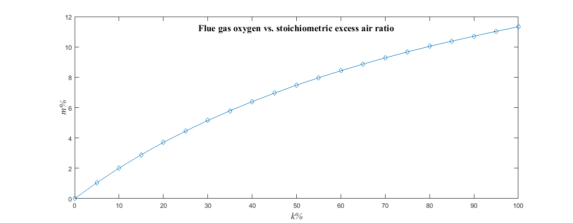
The above figure clearly shows that the oxygen level has one-to-one relationship with the excess air ratio; therefore, flue gas oxygen level can be used in BMS to monitor FARC.
Note the above ratio refers to the stoichiometric excess air ratio. In practice, the FARC is often tuned to have 10% excess air ratio; the air flow rate is presented as the relative air flow with 10% excess air ratio.
If the CCS for boilers and fired heaters have flue gas analyzer installed, BMS can use the oxygen low signal from the analyzer as the fuel/air ratio trip initiator. Oxygen analyzers usually come with both analog outputs for oxygen readings and discrete digital outputs for oxygen low alarm status. The analog reading can be used in CCS for air trim control and digital output used for BMS trip purpose. This method is simple and easy to implement with minimal engineering design effort. If CCS does not have oxygen analyzer, additional analyzer and installation cost are required. Also, the analyzer is a relatively complicated instrument and its reliability rating is usually not as high as common transmitter, such as pressure or temperature. For example, the dangerous failure rate of an analyzer is typically one order of magnitude higher than a pressure transmitter. These are the disadvantages of using analyzer for BMS trip.
Fuel Air Ratio Calculation
BMS can also calculate the fuel air ratio based on measured or inferred air flow and fuel flow. Using direct measurement of air and fuel flows makes the BMS logic simple and provides redundant measurement, but introduces extra instrument hardware cost.
Fuel safety code requires air flow low-low trip and therefore most BMS has independent air flow measurement. However, fuel flow measurement is usually not installed in BMS. One way to solve this problem is to use the inferred (calculated) fuel flow rate based on the fuel pressure at the burner inlet. Burner pressure measurement is already available in BMS because of high pressure trip code requirement and no additional transmitter is required.
Let denote the burner fuel pressure, the maximum gas pressure at 100% burner capacity, the relative air flow in terms of burner load percentage. Then, the following equation calculates the air-to-fuel ratio:
This equation is based on the fact that fuel flow has the square root relationship with burner fuel pressure. This relationship is expected as burner can be viewed as an orifice discharging fuel to firebox at roughly atmospheric pressure. Note the calculated ratio needs to be interpreted based on the meaning of the relative air flow. For example, the relative air flow may be based on 10% excess air or stoichiometric combustion air flow. The same ratio value indicates different combustion condition for these two different relative air flows.
This ratio calculation can be implemented in BMS without additional instruments. It is also more reliable compared with using analyzer trip because it relies on common pressure transmitters only. The disadvantage is the effort of gathering burner data and implementing calculation algorithm in BMS.
Field Data Validation
The methods discussed above have been successfully implemented in multiple fuel appliances, such as industrial boilers, heaters, and vaporizers. This section provides some field data plots as a validation of this method.
Figure 2 below shows the plot between the fuel gas flow and burner fuel pressure. To further illustrate the square root relationship, Figure 3 plots the fuel gas flow and the square root of burner pressure. Clearly, the fuel flow changes according to the square root of the burner pressure.
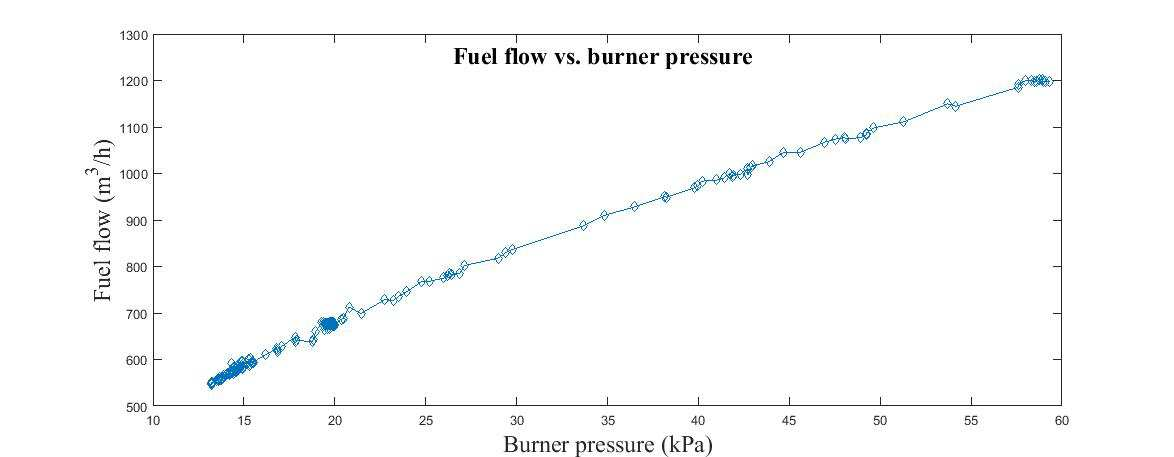
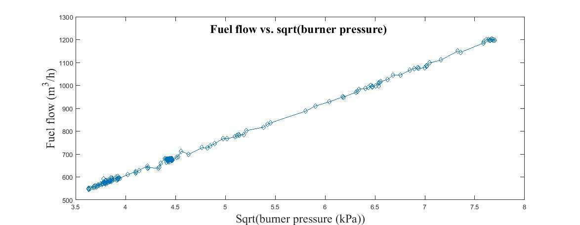
Figure 4 below shows the plot of the measured flue gas oxygen and calculated fuel air ratio. Note in this fuel air ratio calculation, the ratio is between the measured relative air and the calculated required air based on fuel flow estimate. For example, ratio = 120% means the measured relative air from the combustion air flow transmitter is 20% higher than the required air flow.
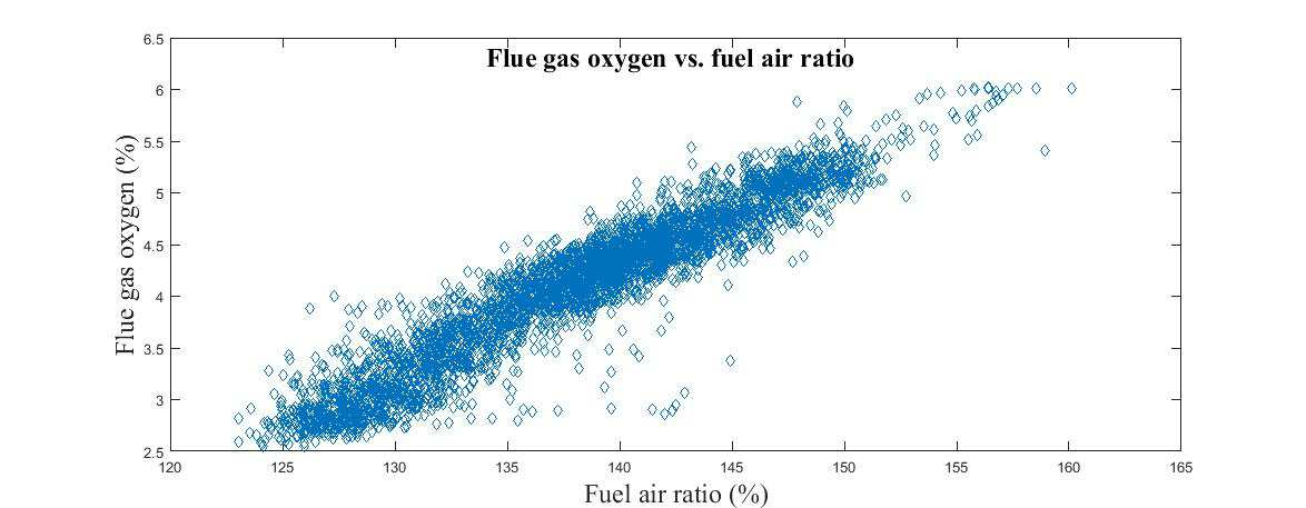
Figure 4 shows the linear correlation between flue gas oxygen and the calculated fuel air ratio; it also shows the measurement noise and uncertainties caused by the oxygen analyzer, pressure transmitters, and fuel flow estimation. Therefore, it is recommended to apply 2-out-2 voting in practice between flue gas oxygen and fuel air ratio calculation to reduce the probability of spurious trip.
Summary
This article discusses two methods of implementing independent FARC monitoring in BMS to comply with regulatory fuel safety code requirement. The advantage and disadvantage of these two methods are listed as follows:
Flue gas oxygen monitoring
- Advantage: Less engineering/design work; easy to understand.
- Disadvantage: May cause false trip because of faulty analyzer; may need to install redundant expensive oxygen analyzer for reliability.
Fuel/air ratio calculation
- Advantage: More reliable results (no analyzer involved in BMS trip); utilizes existing pressure measurements for gaseous fuel.
- Disadvantage: Requires burner data information; more engineering/design work to implement the calculation algorithm.
Engineers and designers may consider these characteristics and specific design requirements and circumstances when implementing FARC monitoring in BMS. For example, to minimize spurious trip rate, 2-out-2 voting can be implemented such that trip initiates only when both flue gas oxygen reading and fuel/air ratio calculation trip are abnormal. Although not a code requirement, Safety Integrity Level (SIL) analysis can be completed to verify that BMS provides adequate protection and acceptable spurious trip rate.
Related Tool: Try the interactive Combustion Calculator to compute stoichiometric air flow, excess-air requirements, and forecasted stack O₂ for natural gas and hydrogen firing.